
VHF-UHF Long Boom, Ultra High Performance Antenna Designs
(links updated 27 Sep 2016)
Ultra High Performance Yagis are defined (by me) to be those Yagi antennas with a F/R (Front/Rear) greater than 30 dB in both planes, first sidelobe levels of -20 dB or better and gain at or above the DL6WU gain curve. These antennas will also have a very high G/T, but this is not the only performance feature that defines what I consider to be the Best of the Best. These long Yagi antennas are definitely suited for EME operation, but can be used to significantly reduce noise sources for terrestrial communications too.
The DL6WU gain curve can be written as GAIN (dBi) = 7.773 * LOG (Length / Lambda) + 11.43
Another good gain curve for yagis is given by Tom Ring, WA2PHW/K0TAR: Gain (dBd) = 10 * LOG (5.4075 * (Length/Lambda) + 4.25)
As you can see, very few antenna models can meet this criteria and be called Ultra High Performance. In fact, if I were to strictly sort out the 50 MHz designs, all would consist of designs with boom lengths greater than 82 feet (22 m). So, in order to show a few more worthy designs, I have relaxed my definition slightly for the lower VHF/UHF bands.
50 MHz band: F/R >= 25 dB, first sidelobe better than -18 dB
144 MHz band: F/R >= 26 dB, first sidelobe better than -19 dB
222 MHz band: F/R >= 28 dB, first sidelobe better than -19 dB
432 MHz band: F/R >= 29 dB, first sidelobe better than -20 dB
902 MHz band: F/R > 30 dB, first sidelobe better than -20 dB
1296 MHz band: F/R > 30 dB, first sidelobe better than -20 dB
From these tables
and NEC
files, you can compare the performance between the various
models. Please feel free to contribute your own designs to this
collection.
| Model | Directive Gain (dBi) | G/T | E-F/R (dB) | H-F/R (dB) | Boom Length (feet) | Boom Length (m) | NEC file | EZNEC file | Az Pattern | Elev Pattern |
| - | - | - | - | - | - | - | - | - | - | |
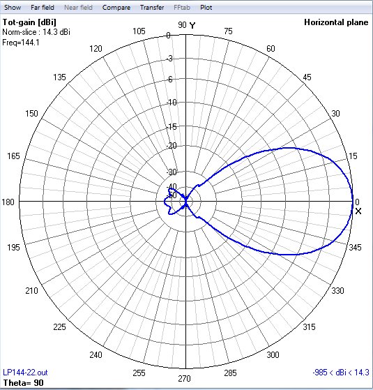
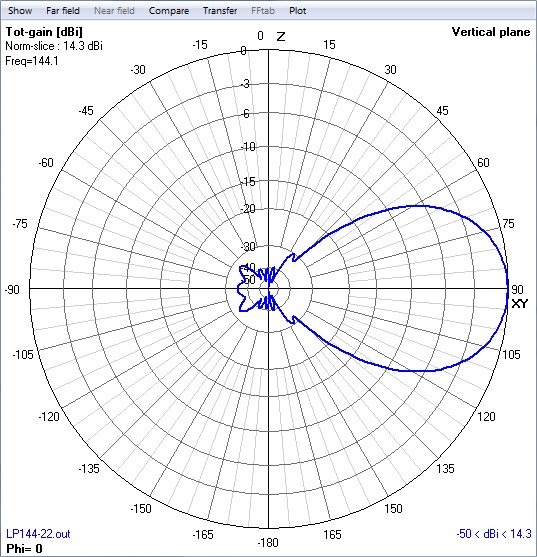
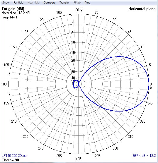
| W8IO-LP144-22 | 14.3 | - | 35 | 35 | 22 | - | LP144-22 | LP144-22 | LP144-22-az | LP144-22-el |
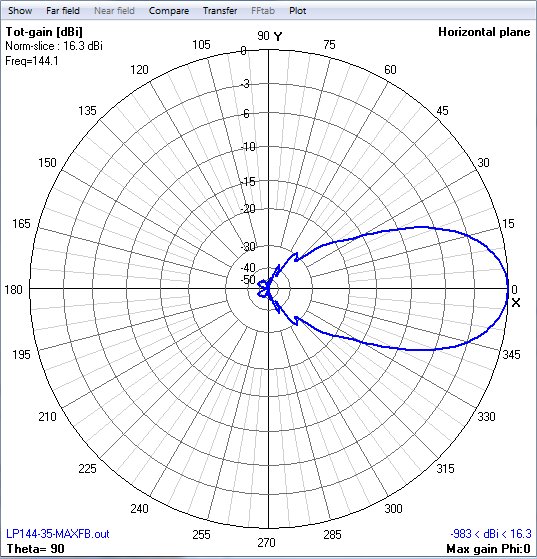
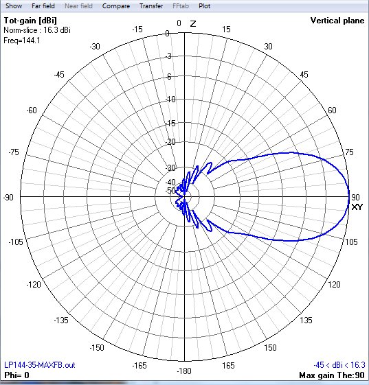
| W8IO-LP144-35-MAXFB | 16.34 | - | 48 | 37 | 32 | 9.7 | LP144-35MAXFB | LP144-35MAXFB | LP144-35-MFB-az | LP144-35-MFB-el |
| - |
- |
- | - |
- | - |
- | - | - | ||
| - | - | - | - | - | - | - | - | - | - |
50 MHz long boom Yagi NEC files (30-45 foot booms)
| Model | Directive Gain (dBi) | E-F/R (dB) | H-F/R (dB) | E-SLL (dB) | H-SLL (dB) | Boom Length (feet) | Boom Length (m) | Boom Length (lambda) | NEC file | EZNEC file | Az Pattern | Elev Pattern | Best US Price (Dec 8) |
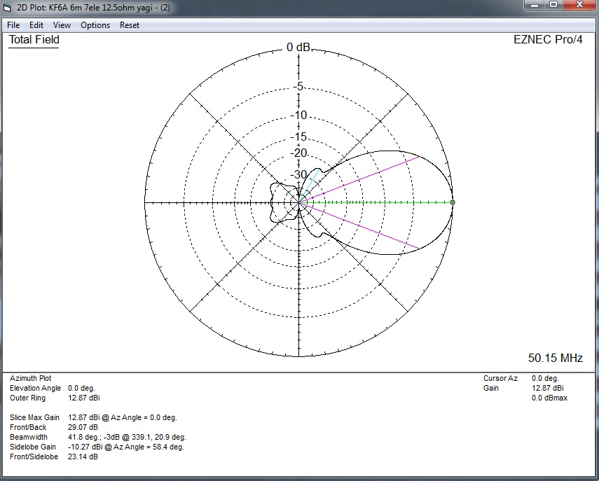
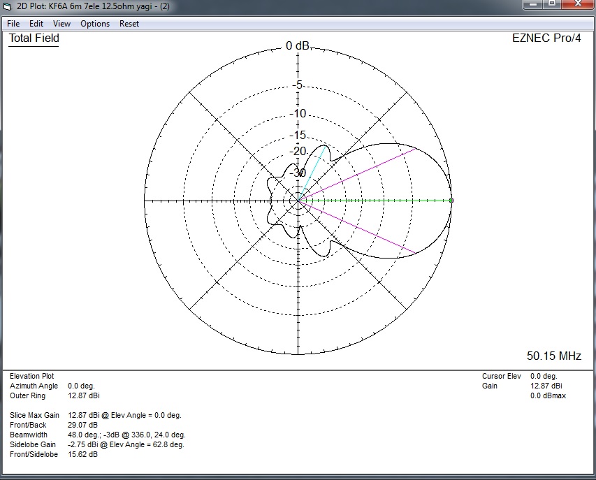
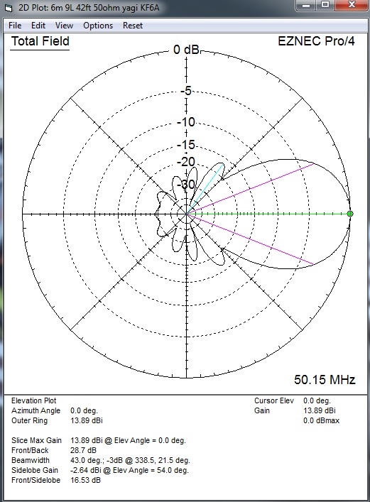
| KF6A-50-7L | 12.98 | 26.57 | 24.28 | -23.2 | -15.6 | 29.2 | 8.9 | - | KF6A-7L | KF6A-7L | KF6A-7L-az | KF6A-7L-el | - |
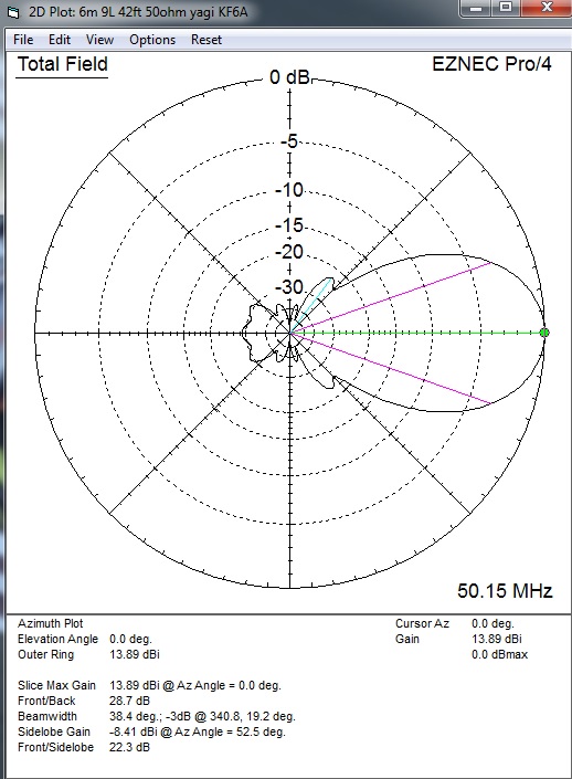
| KF6A-50-9L | 13.95 | 28.69 | 24.59 | -22.4 | -16.5 | 42 | 12.8 | - | KF6A-9L | KF6A-9L | KF6A-9L-az | KF6A-9L-el | - |
The antennas shown in red are experimental and have not yet been built or tested. F/R includes all backlobes.
144
MHz long boom Yagi NEC files (25-42 foot booms)
| Model | Directive Gain (dBi) |
VE7BQH G/T (dB) |
+/- Gain (DL6WU equation) |
YagiCAD G/T (dB) |
E-F/R (dB) | H-F/R (dB) | E-SLL (dB) |
H-SLL (dB) |
Boom Length (feet) | Boom Length (m) | Boom Length (lambda) |
NEC file | EZNEC file | Az Pattern | Elev Pattern |
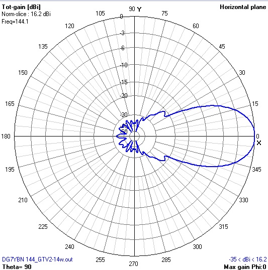
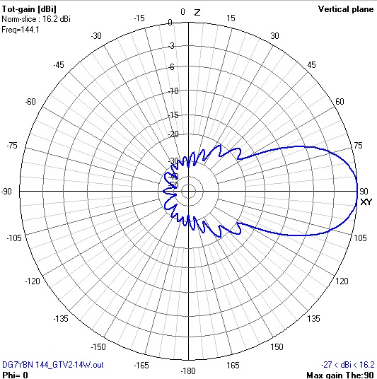
| DG7YBN 144-GTV2-14w | 16.30 | -1.20## | +0.21 | - | 33.27 | 28.1 | -20.7 | -17.3 | 27.16 | 8.28 | 4.0 | DG7YBN GTV2-14w | GTV2-14w | GTV2-14w-az | GTV2-14w-el |
| W8IO-144-14V* | 16.27 | -1.18* | +0.18 | - | 34.06 | 30.04 | -21.2 | -17.7 | 27.16 | 8.28 | 4.0 | 144-14V | 144-14V | 144-14V-az | 144-14V-el |
| W8IO-144-15V | 16.58 | -0.80** | +0.15 | - | 34.33 | 31.53 | -20.7 | -17.5 | 30.0 | 9.14 | 4.4 | 144-15V | 144-15V | 144-15V-az | 144-15V-el |
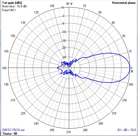
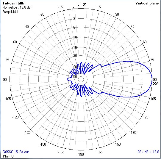
| G0KSC-15LFA-EU | 16.83 | -0.48** | +0.16 | - | 29.16 | 26.14 | -22.5 | -19.6 | 32.3 | 9.85 | 4.73 | 144-15LFA | 144-15LFA | 144-15LFA-az | 144-15LFA-el |
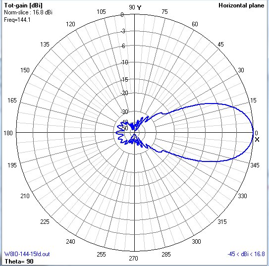
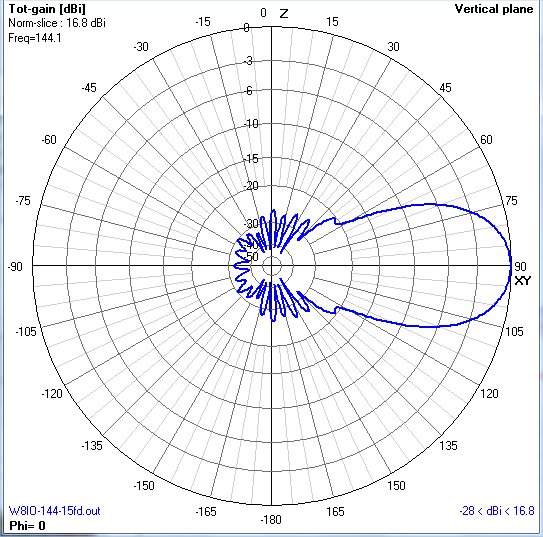
| W8IO-144-15FD | 16.81 | -0.57** | +0.14 | - | 32.33 | 27.11 | -23.2 | -20.5 | 32.3 | 9.85 | 4.73 | 144-15FD | 144-15FD | 144-15FD-az | 144-15FD-el |
| W8IO-144-16V | 16.87 | -0.55** | +0.20 | - | 35.8 | 32.3 | -19.6 | -16.8 | 32.3 | 9.86 | 4.73 | 144-16V | 144-16V | 144-16V-az | 144-16V-el |
| W8IO-144-16V2 | 16.95 | -0.59** | +0.28 | - | 31.78 | 30.15 | -18.8 | -16.1 | 32.3 | 9.86 | 4.73 | 144-16V2 | - | 144-16V2-az | 144-16V2-el |
| W8IO-UR5EAZ-16V* | 16.94 | -0.45*** | +0.27 | - | 36.15 | 32.18 | -19.2 | -16.4 | 32.3 | 9.85 | 4.73 | W8IO-UR5EAZ | W8IO-UR5EAZ | 16V-az | 16V-el |
| W8IO-144-17V | 17.11 | -0.27*** | +0.18 | - | 35.48 | 32.34 | -19.2 | -16.5 | 34.8 | 10.6 | 5.1 | 144-17V | 144-17V | 144-17V-az | 144-17V-el |
| W8IO-144-18V | 17.29 | -0.09*** | - | - | 35.54 | 32.69 | -18.7 | -16.2 | 37 | 11.3 | 5.43 | 144-18V | 144-18V | 144-18V-az | 144-18V-el |
| W8IO-144-18V2 | 17.42 | -0.07*** | +0.28 | - | 34.08 | 30.07 | -17.9 | -15.5 | 37 | 11.3 | 5.43 | 144-18V2 | 144-18V2 | 144-18V2-az | 144-18V2-el |
| W8IO-144-19V | 17.62 | +0.17*** | +0.234 | - | 34.81 | 32.37 | -17.9 | -15.6 | 39.9 | 12.15 | 5.84 | 144-19V | 144-19V | 144-19V-az | 144-19V-el |
| W8IO-144-20V | 17.87 | +0.36*** | +0.28 | - | 37.04 | 31.63 | -17.7 | -15.6 | 42 | 12.9 | 6.2 | 144-20V | 144-20V | 144-20V-az | 144-20V-el |
The antennas shown in red are experimental and have not yet been built or tested. The antennas shown with * have complete instructions for building. F/R includes all backlobes. For the YagiCAD G/T, Tsky=200 and Tearth = 1000.
## These G/T values are calculated based on stacking distances of 4.2m (E-plane) and 4.0m (H-plane).
* These G/T values are calculated based on stacking distances of 4.4m (E-plane) and 4.2m (H-plane).
** These G/T values are calculated based on stacking distances of 4.6m (E-plane) and 4.4m (H-plane).
*** These G/T values are calculated based on stacking distances of 4.8m (E-plane) and 4.6m (H-plane).
222 MHz long boom Yagi NEC files (25-35 foot booms)
| Model | Directive Gain (dBi) |
+/- Gain (DL6WU equation) |
YagiCAD G/T (dB) |
E-F/R (dB) | H-F/R (dB) | E-SLL (dB) |
H-SLL (dB) |
Boom Length (feet) |
Boom Length (m) |
Boom Length (Lambda) |
NEC file | EZNEC file | YagiCAD file | Az Pattern | Elev Pattern |
| W8IO-222-15V | 16.61 | +0.18 | - | 34.39 | 31.3 | -20.6 | -17.6 | 19.5 | 5.9 | 4.4 | W8IO-222-15V | W8IO-222-15V | W8IO-222-15V | W8IO-222-15V-az | W8IO-222-15V-el |
| W8IO-222-16V | 16.9 | +0.22 | - | 35.71 | 31.48 | -19.6 | -16.9 | 21 | 6.4 | 4.74 | W8IO-222-16V | W8IO-222-16V | W8IO-222-16V | W8IO-222-16V-az | W8IO-222-16V-el |
| W8IO-222-17V | 17.15 | +0.22 | - | 34.77 | 31.76 | -19.1 | -16.9 | 22.56 | 6.88 | 5.1 | W8IO-222-17V | W8IO-222-17V | W8IO-222-17V | W8IO-222-17V-az | W8IO-222-17V-el |
| W8IO-222-18V | 17.33 | +0.19 | - | 35.54 | 32.69 | -18.6 | -16.3 | 24 | 7.33 | 5.43 | W8IO-222-18V | W8IO-222-18V | W8IO-222-18V | W8IO-222-18V-az | W8IO-222-18V-el |
| W8IO-222-19V | 17.58 | - | - | 37.76 | 36.28 | -18.0 | -15.8 | 25.87 | 7.887 | 5.84 | W8IO-222-19V | W8IO-222-19V | W8IO-222-19V | W8IO-222-19V-az | W8IO-222-19V-el |
| W8IO-222-18 | 18.14 | +0.53 | -1.71 | 30.9 | 28.7 | -20.1 | -18.4 | 27.6 | 8.43 | 6.24 | W8IO-222-18 | W8IO-222-18 | W8IO-222-18 | W8IO-222-18-az | W8IO-222-18-el |
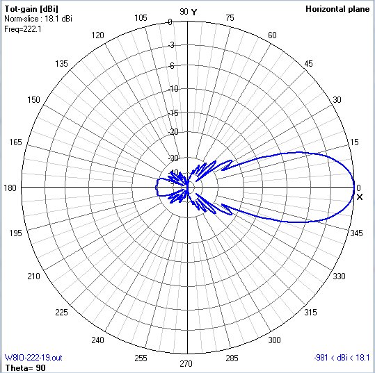
| W8IO-222-19 | 18.12 | +0.24 | -1.3 | 29.05 | 28.42 | -21.4 | -19.7 | 30 | 9.1 | 6.76 | W8IO-222-19 | W8IO-222-19 | W8IO-222-19 | W8IO-222-19az | W8IO-222-19el |
The antennas shown in red are experimental and have not yet been built or tested. F/R includes all backlobes. For the YagiCAD G/T, Tsky=70 and Tearth = 600.
432 MHz long boom Yagi NEC files
(17-25 foot booms)
| Model | Directive Gain (dBi) | VE7BQH G/T (dB) |
+/- Gain (DL6WU equation) |
YagiCAD G/T (dB) |
E-F/R (dB) | H-F/R (dB) | E-SLL (dB) |
H-SLL (dB) |
Boom Length (feet) | Boom Length (m) | Boom Length (Lambda) |
NEC file | EZNEC file | YagiCAD File |
Az Pattern | Elev Pattern |
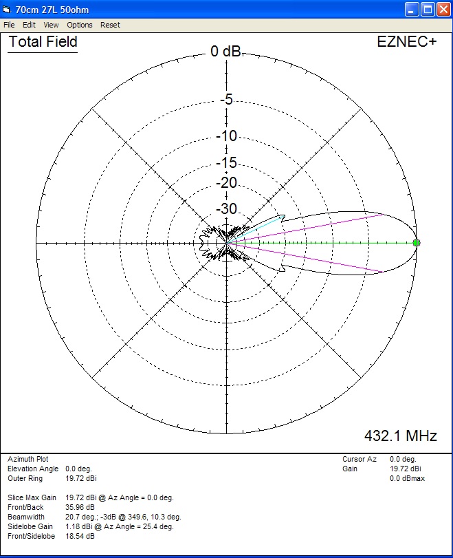
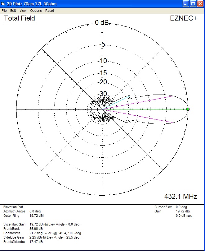
| KF6A-432-27 | 19.72 | 10.77 | +0.43 | 5.08 | 33.08 | 31.69 | -18.6 | -17.5 | 23.36 | 7.12 | 10.27 | KF6A-432-27 | KF6A-432-27 | KF6A-432-27 | KF6A-432-27-az | KF6A-432-27-el |
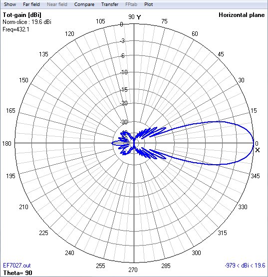
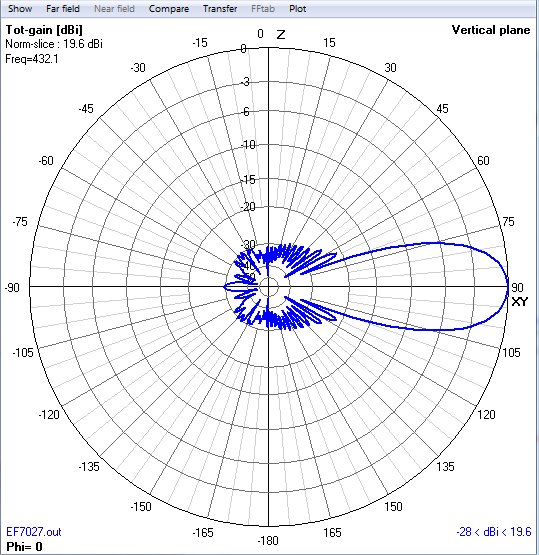
| YU7EF EF7027 | 19.58 | 10.39 | +0.25 | 4.76 | 29.5 | 29.5 | -22.3 | -21.2 | 23.75 | 7.2 | 10.4 | EF7027 | EF7027 | EF7027 | EF7027-az | EF7027-el |
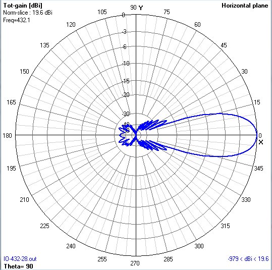
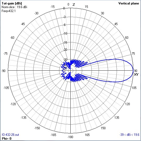
| W8IO-432-28 | 19.69 | - | +0.23 | 4.89 | 32.7 | 30.8 | -23 | -22 | 24.6 | 7.5 | 10.8 | W8IO-432-28 | W8IO-432-28 | W8IO-432-28 | W8IO-432-28az | W8IO-432-28el |
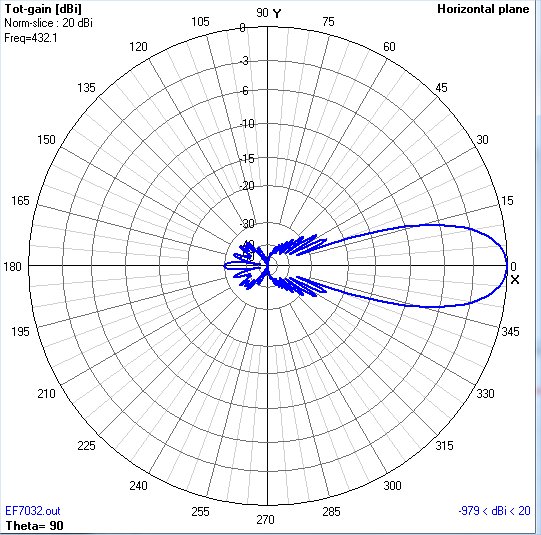
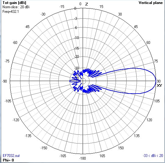
| YU7EF EF7032 |
20.02 | 10.84 | +0.07 | 5.3 | 29.81 | 29.81 | -23.9 | -22.9 | 28.4 | 8.67 | 12.49 | EF7032 | EF7032 | EF7032 | EF7032-az | EF7032-el |
902 MHz long boom Yagi NEC files
(6-20 foot booms)
| Model | Directive Gain (dBi) | G/T | E-F/R (dB) | H-F/R (dB) | Boom Length (feet) | Boom Length (m) | NEC file | EZNEC file | Az Pattern | Elev Pattern | Best US Price | |
These antennas have been built, tested and are currently in use.
1296 MHz long boom Yagi NEC files (10-20 foot booms)
| Model | Directive Gain (dBi) | G/T | E-F/R (dB) | H-F/R (dB) | Boom Length (feet) | Boom Length (m) | NEC file | EZNEC file | Az Pattern | Elev Pattern | Best US Price |
These antennas have been built, tested and are currently in use.
The performance numbers listed in the tables above are from my NEC2 and NEC4 simulations except for the G/T values, which come from VE7BQH's tables. These numbers will vary slightly due to factors such as element segmentation density and losses due to aluminum conductivity.
Element Length Correction due to Boom
The VHF/UHF antenna NEC files shown above include the "raw" element lengths. That is, the element lengths are those used with a wood or plastic (dielectric) boom or supported above or below a metal boom with an large insulator. To convert these raw lengths into actual lengths used when passed through the center of metal booms, you need to add a correction factor, based on whether the element is insulated and passes through the center of a metal boom, or is shorted directly to the metal boom with a clamp. If the element is insulated when it passes through the metal boom, the correction factor is approximately 15% the diameter of the boom. For example, for a 36" (raw length) insulated element passed through the center of a 1" metal boom, the YU7EF correction factor is 0.15", so the actual length should be 36.15" when built. The table below gives correction factors for common US boom diameters.
| Boom Diameter (inches) | DL6WU/G3SEK insulated element THRU metal boom correction factor (inches) | YU7EF insulated element THRU metal boom correction factor (inches) | YU7EF insulated element ABOVE metal boom correction factor (inches) |
| 0.875 | 0.106 | 0.125 | 0.031 |
| 1.000 | 0.137 | 0.150 | 0.0375 |
| 1.125 | 0.170 | 0.188 | 0.047 |
| 1.250 | 0.206 | 0.215 | 0.0538 |
| 1.375 | 0.246 | 0.255 | 0.0638 |
| 1.500 | 0.289 | 0.295 | 0.0738 |
| 1.625 | 0.333 | 0.340 | 0.085 |
| 1.750 | 0.380 | 0.385 | 0.096 |
Various antenna experimentors have similar correction factors, as shown below.
Here is a link to YU7EF's Boom Correction Notes.
Here is a link to YU1AW's Boom Correction article.
Here is information from the VHF/UHF Long Yagi Workshop.
Here is a link to DG7YBN's Boom Correction Notes and his Practical Yagi Building page.
Here is a link to SM5BSZ's collection of Boom Correction information.
The plastic element insulators and stainless steel keepers may be purchased from Directive Systems here in the US.Here are some ideas and hints to help with your home antenna construction.
Comments and corrections/additions are welcome!
contact Roger: email to
rgcox2 (at) gmail.com
Roger Cox W8IO - Spring Lake, MI